CSJA JCN/EG
In-Line Cold Shrinkable Joints Specifically for 1/C Jacketed Concentric Neutral Cables (15-35 kV)
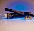
TE’s Raychem “All-in-One” CSJA is a cold shrinkable joint for 15 kV through 35 kV. It is designed to
splice jacketed concentric neutral (JCN) cables.
- Cable joint has a pre-expanded EPDM rejacketing sleeve and an integrated neutral sock.
The “All-in-One” design is easy to install with minimal steps and short installation time
- A pre-expanded, single-piece silicone rubber joint body with high mechanical expansion capability
allows a wide application range
- An ergonomically designed spiral holdout provides a smooth installation with low release forces.
- Total length of the splice body on the holdout is 14 to 19 inches providing a compact design.
- The Silicone rubber body provides high dielectric strength, high tear strength, low tension set, and
excellent low temperature recovery
- Integrated electrical stress control enhanced by factory molded stress cones and Faraday cage.
- Void filling stress relief mastics are not necessary.
- Proven shield continuity concept. The neutral wires are connected externally. The integrated pre-expanded neutral sock is connected to the neutral wires by a constant force spring. This provides
the metallic shielding system to the cable joint.
- The joint accepts both mechanical and compression connectors.
- Meets IEEE-404 requirements for 15 kV through 35 kV.
Each silicone splice body is factory tested to include AC withstand and partial discharge in
accordance with IEEE-404 production tests.
Selection Information:
Commonly used CSJA JCN/EG Joints Without Connector
CSJA-JCN/EG-1511 is supplied with a Voltage Class of 15 kV and a Nominal Cable Range of #2-350. The Insulation O.D. range is 17.5-30.5 mm (A) with a Maximum Jacket O.D. of 38.1 mm (B). The Maximum Connector Dimensions include an O.D. of 33 mm (C) and a Length of 140 mm (D).
CSJA-JCN/EG-1512 is supplied with a Voltage Class of 15 kV and a Nominal Cable Range of 4/0-750. The Insulation O.D. range is 22.1-35.6 mm (A) with a Maximum Jacket O.D. of 46 mm (B). The Maximum Connector Dimensions include an O.D. of 38 mm (C) and a Length of 140 mm (D).
CSJA-JCN/EG-1513 is supplied with a Voltage Class of 15 kV and a Nominal Cable Range of 350-1000. The Insulation O.D. range is 26.2-40 mm (A) with a Maximum Jacket O.D. of 52.1 mm (B). The Maximum Connector Dimensions include an O.D. of 42 mm (C) and a Length of 170 mm (D).
CSJA-JCN/EG-1514 is supplied with a Voltage Class of 15 kV and a Nominal Cable Range of 750-1250. The Insulation O.D. range is 32.5-52 mm (A) with a Maximum Jacket O.D. of 66 mm (B). The Maximum Connector Dimensions include an O.D. of 47 mm (C) and a Length of 200 mm (D).
CSJA-JCN/EG-2812 is supplied with a Voltage Class of 28 kV and a Nominal Cable Range of #1-500. The Insulation O.D. range is 22.1-35.6 mm (A) with a Maximum Jacket O.D. of 46 mm (B). The Maximum Connector Dimensions include an O.D. of 38 mm (C) and a Length of 140 mm (D).
CSJA-JCN/EG-2813 is supplied with a Voltage Class of 28 kV and a Nominal Cable Range of 4/0-750. The Insulation O.D. range is 26.2-40 mm (A) with a Maximum Jacket O.D. of 52.1 mm (B). The Maximum Connector Dimensions include an O.D. of 42 mm (C) and a Length of 170 mm (D).
CSJA-JCN/EG-2814 is supplied with a Voltage Class of 28 kV and a Nominal Cable Range of 500-1250. The Insulation O.D. range is 32.5-52 mm (A) with a Maximum Jacket O.D. of 66 mm (B). The Maximum Connector Dimensions include an O.D. of 47 mm (C) and a Length of 200 mm (D).
CSJA-JCN/EG-3513 is supplied with a Voltage Class of 35 kV and a Nominal Cable Range of 1/0-350. The Insulation O.D. range is 26.2-37.8 mm (A) with a Maximum Jacket O.D. of 52.1 mm (B). The Maximum Connector Dimensions include an O.D. of 35.6 mm (C) and a Length of 140 mm (D).
CSJA-JCN/EG-3514 is supplied with a Voltage Class of 35 kV and a Nominal Cable Range of 350-1000. The Insulation O.D. range is 34.54-52 mm (A) with a Maximum Jacket O.D. of 66 mm (B). The Maximum Connector Dimensions include an O.D. of 50 mm (C) and a Length of 200 mm (D).
CSJA-JCN/EG-3515 is supplied with a Voltage Class of 35 kV and a Nominal Cable Range of 750-1250. The Insulation O.D. range is 41.4-60 mm (A) with a Maximum Jacket O.D. of 66 mm (B). The Maximum Connector Dimensions include an O.D. of 60 mm (C) and a Length of 200 mm (D).
Commonly used CSJA JCN/EG Joints with Copper Mechanical ShearBolt Connector
CSJA-JCN/EG-1511M1 is supplied with a Voltage Class of 15 kV and a Nominal Cable Range of 2/0-350. The Insulation O.D. range is 17.5-30.5 mm (A) with a Maximum Jacket O.D. of 38.1 mm (B). The Diameter Over Cable Conductor range is 9.5-18.7 mm.
CSJA-JCN/EG-1512M1 is supplied with a Voltage Class of 15 kV and a Nominal Cable Range of 4/0-500. The Insulation O.D. range is 22.1-35.6 mm (A) with a Maximum Jacket O.D. of 46 mm (B). The Diameter Over Cable Conductor range is 9.5-18.7 mm.
CSJA-JCN/EG-1512M2 is supplied with a Voltage Class of 15 kV and a Nominal Cable Range of 350-750. The Insulation O.D. range is 22.1-35.6 mm (A) with a Maximum Jacket O.D. of 46 mm (B). The Diameter Over Cable Conductor range is 14.5-24 mm.
CSJA-JCN/EG-1513M2 is supplied with a Voltage Class of 15 kV and a Nominal Cable Range of 350-750. The Insulation O.D. range is 26.2-40 mm (A) with a Maximum Jacket O.D. of 52.1 mm (B). The Diameter Over Cable Conductor range is 14.5-24 mm.
CSJA-JCN/EG-2812M1 is supplied with a Voltage Class of 28 kV and a Nominal Cable Range of 2/0-500. The Insulation O.D. range is 22.1-35.6 mm (A) with a Maximum Jacket O.D. of 46 mm (B). The Diameter Over Cable Conductor range is 9.5-18.7 mm.
CSJA-JCN/EG-2813M2 is supplied with a Voltage Class of 28 kV and a Nominal Cable Range of 350-750. The Insulation O.D. range is 26.2-40 mm (A) with a Maximum Jacket O.D. of 52.1 mm (B). The Diameter Over Cable Conductor range is 14.5-24 mm.
CSJA-JCN/EG-2814M2 is supplied with a Voltage Class of 28 kV and a Nominal Cable Range of 500-750. The Insulation O.D. range is 26.2-40 mm (A) with a Maximum Jacket O.D. of 52.1 mm (B). The Diameter Over Cable Conductor range is 14.5-24 mm.
CSJA-JCN/EG-3513M1 is supplied with a Voltage Class of 35 kV and a Nominal Cable Range of 2/0-350. The Insulation O.D. range is 26.2-37.8 mm (A) with a Maximum Jacket O.D. of 52.1 mm (B). The Diameter Over Cable Conductor range is 9.5-18.7 mm.
CSJA-JCN/EG-3514M2 is supplied with a Voltage Class of 35 kV and a Nominal Cable Range of 350-750. The Insulation O.D. range is 34.54-52 mm (A) with a Maximum Jacket O.D. of 66 mm (B). The Diameter Over Cable Conductor range is 14.5-24 mm.